In this tutorial I’ll show you how to use a $3.50 RF remote, a $2 RF receiver, and a Raspberry Pi to control a WiFI LED Light Bulb.
Why
Smart LED light bulbs are great, but having to get your phone out every time you want to turn your lights on or off isn’t.
Philips sell a AU$34 dimmer switch that works with the Hue lighting system and other Zigbee-based lighting systems (in theory at least).
However I’ve decided to go with LIFX WiFi light bulbs, and the options for a physical button/switch aren’t great:
- Flic - US$35 per button, relies on your smartphone as a bluetooth-wifi bridge, not officially sold in Australia
- Logitech - US$100 for 2 buttons and a hub, not officially sold in Australia
- Logitech Harmony - AU$49 for remote + AU$150 for a hub
I believe all of these use the LIFX cloud API rather than the LIFX LAN protocol, meaning they’ll also be a bit slow.
And I’m not the only one unhappy with the situation, as indicated by many posts on reddit.
Stuff you need
- One or more RF remote controls with a EV1527 encoder. I’m using one with 4 buttons that cost AU$3.50 on eBay. Just search eBay or AliExpress for EV1527 and buy one you like the look of. Check that the frequency and power level is legal in your country. 433MHz and <25mW is perfectly legal in Australia.
- An RF receiver/decoder that’s compatible with your remote. I’m using one designated RXC6 that cost AU$2 on eBay. Here are the key requirements to make sure it’s compatible:
- Must be same frequency of your remote
- Must mention “EV1527”
- Must have 4 output data pins (numbered D0-D3 or D1-D4)
- Must have a button on it, or mention something about “learning”
- Home Assistant - this is a piece of software that turns a Raspberry Pi into a home automation controller.
- A Raspberry Pi - I’m using a RPi 3 Model B. I couldn’t get Home Assistant to install on my RPi 1; a RPi 2 might work.
- A microSD card for your Raspberry Pi.
- Some jumper (aka DuPont) cables to connect the RF receiver to your Raspberry Pi.
- A Wifi-controlled LED light bulb, e.g. LIFX, already set up on your Wifi network.
Connect the RF receiver/decoder to the Raspberry Pi
Connect as follows:
- RXC6 GND -> RPI GND
- RXC6 VDD -> RPI 5V
- RXC6 D0 -> RPI GPIO 20 (or any available GPIO)
- RXC6 D1 -> RPI GPIO 21 (or any available GPIO)
- RXC6 D2 -> RPI GPIO 22 (or any available GPIO)
- RXC6 D3 -> RPI GPIO 23 (or any available GPIO)
- RXC6 VT -> RPI GPIO 24 (or any available GPIO)
NB GPIO numbers are not the same as pin header numbers:
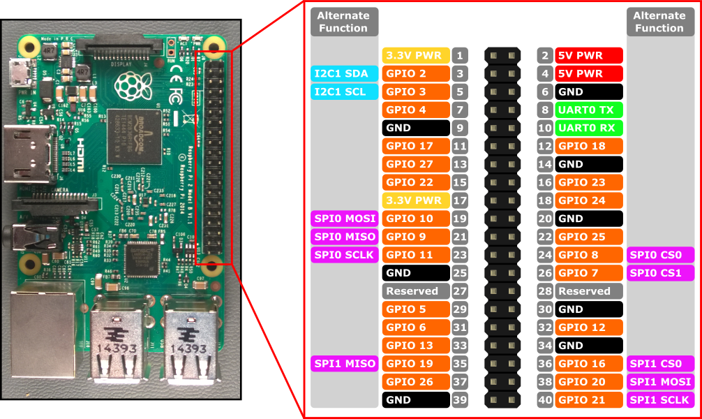
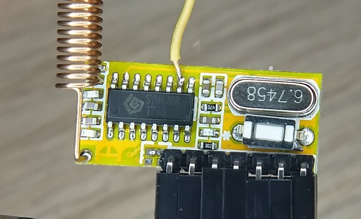
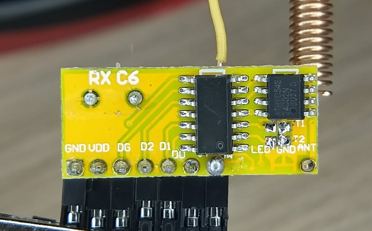
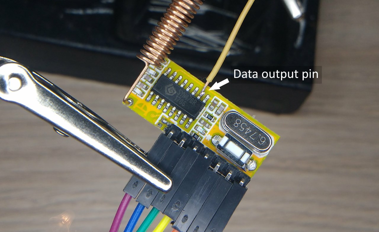
The RXC6 pins should be labelled on the PCB. Make sure you solder an antenna to the RXC6. I’m using a pre-wound 433MHz pre-wound helical antenna that cost AU$0.17 on eBay; the next best thing is a 1⁄4 wavelength long piece of (ideally) solid core wire. For 433MHz: λ/4 = c/4f = 300,000,000/(4*433,000,000) = 0.173m.
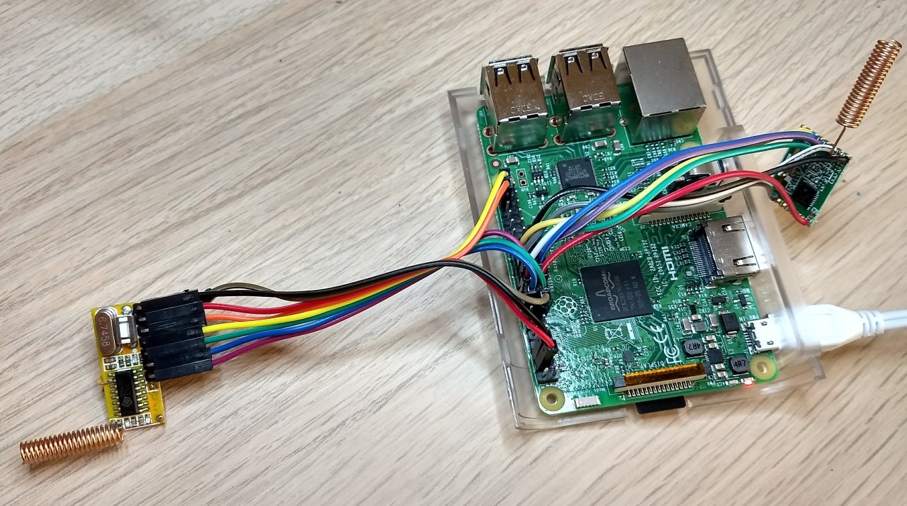
Mine looked like this (RXC6 is on the left; I also have a RFM69 radio transceiver connected on the right because I’m using my RPi as a MySensors gateway):
Set up Home Assistant
Install Home Assistant
Follow instructions on the Home Assistant website to install hassbian on your Raspberry Pi. (hass.io should also work, but I haven’t tested it.)
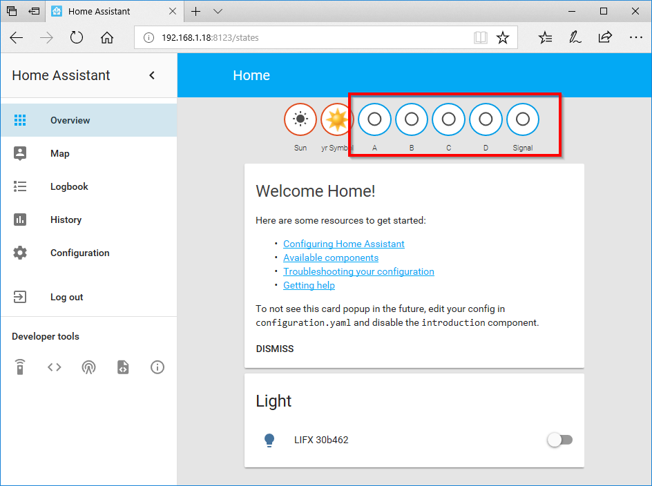
Open the Home Assistant web interface at http://x.x.x.x:8123/ (where x.x.x.x is the IP address of your Raspberry Pi) and you should see something like this:
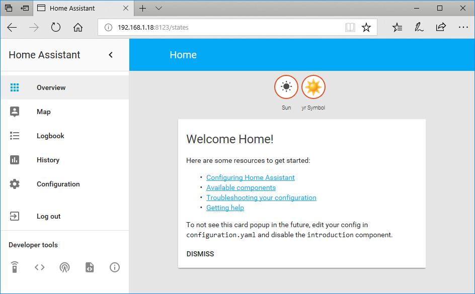
You can now configure Home Assistant by editing the configuration files.
Set up LIFX lights
Add this to configuration.yaml to get Home Assistant to detect your LIFX lights:
# Lights
light:
  - platform: lifx
(Find instructions here if you’re using lights other than LIFX.)
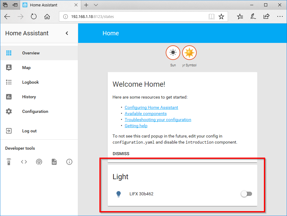
Restart Home Assistant (Configuration->General->Server Management->RESTART) and then you should be able to see your light(s) in Home Assistant:
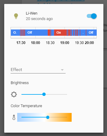
If you click on the light, you’ll get a popup window that lets you control the light from your web browser:
Set up binary sensors on GPIO pins
Add this to configuration.yaml to get Home Assistant to receive commands from the RF decoder via the GPIO pins: (Change the port numbers if you’ve used different GPIO pins.)
#RF Receiver
binary_sensor:
  - platform: rpi_gpio
    ports:
      20: A
      21: B
      22: C
      23: D
      24: Signal
Restart Home Assistant, and then you should be able to see some binary sensors in Home Assistant for each pin on the RF decoder. NB pressing buttons on your remote won’t do anything just yet.
Pair your RF receiver/decoder with your remotes
Each remote is programmed with a random address, so we need to teach the receiver to respond to that address.
- Hold your remote near the RF receiver and press one of the buttons on the remote. The LED on the receiver should flash rapidly to indicate that it’s decoded a valid signal.
- Press the “learning” button on the receiver - the LED on the receiver should light up solid to indicate that it is in learning mode. If the LED doesn’t come on, you might need to hold the button for a few seconds until the LED comes on.
- Press any button on your remote - the LED on the receiver should flash a few times to indicate that it’s learnt your remote’s code.
- If you press any button on your remote again, the LED on the receiver should light up solid to indicate that it’s received a signal from a remote that it’s been paired with.
- Repeat this process for any other remotes you have.
Now, when you press buttons on your remote, you should see the binary sensors change status in Home Assistant. The “Signal” sensor should also come on when any button is pressed. If you press more than one button at once, you should see all the corresponding sensors change.
Here’s a video of the whole process:
How the EV1527 and RXC6 work
This seems like a good point to explain what’s going on with the RF encoder/transmitter and receiver/decoder. (Skip this section if you’re not interested.)
The EV1527 is fairly straightforward - it transmits a 20-bit codeword, comprising 16 address bits followed by 4 data bits. The address is random number programmed into each chip to serve as a unique identifier. The chip has 4 digital inputs - one for each data bit. On my 4-button remote, each button controls one data bit. This also means that the remote can transmit simultaneous button presses, e.g. A=0001, B=0010, A+B=0011. Remotes with more than 4 buttons will typically use a bunch of diodes to encode each button as a number from (decimal) 0 to 15, so pressing two buttons together will transmit the bitwise-OR of the two codes. Datasheets are readily available.
The RXC6 is much more interesting. It uses a SYN470R RF receiver, a 24C02N EEPROM, and an unmarked microcontroller. The “datasheet” is poorly translated; it’s decipherable with some difficulty, except for this baffling description of the two solder jumpers labelled T1 and T2:
(10) Output: minutes jog, self-locking, interlocking optional;
Default (T2, T1 vacant) is jog mode, there are valid signal is input, the corresponding output signals output valid signal is not automatically stop output.
The back panel 2 (T2 grounded, T1 floating) is self-locking mode, the input signal is valid, corresponding to the state of inverted output signal, the output is high before becomes low, and vice versa.
the back panel (T2 vacant, T1 ground) is interlocked mode, the input signal is valid, the output signals corresponding to the outputs, the other closed. Signal indication; when a valid signal is input, VT output high, after the disappearance of VT is a valid signal output low
Here is a better translation:
- T1 & T2 open = momentary action, i.e. pressing a button activates the corresponding output, but it resets when the button is released. Each output operates independently.
- T1 shorted = self-latching action, i.e. pressing a button activates and latches the corresponding output, and resets all other outputs. Pressing two buttons together resets all outputs. Just like the buttons on a cheap pedestal fan.
- T2 shorted = toggle action, i.e. pressing a button activates the corresponding output; press again to reset. Each output operates independently.
The decoder can be paired with several remotes. To unpair from all remotes, press and hold the learning button until the LED flashes a few times. If you want different remotes to do different things, you need to use a separate decoder (or hack the remote so that it encodes its button differently).
Finally, if you want to read the raw RF codes using rpi-rf, you can solder a wire to the data output pin of the RF receiver, and connect it to a Raspberry Pi GPIO.
Configure Button “A” to toggle lights
There are two ways to set up an automation in Home Assistant - I’ll show you both.
Option 1: use the web interface
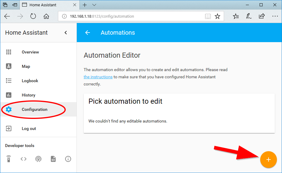
Open the automation editor:
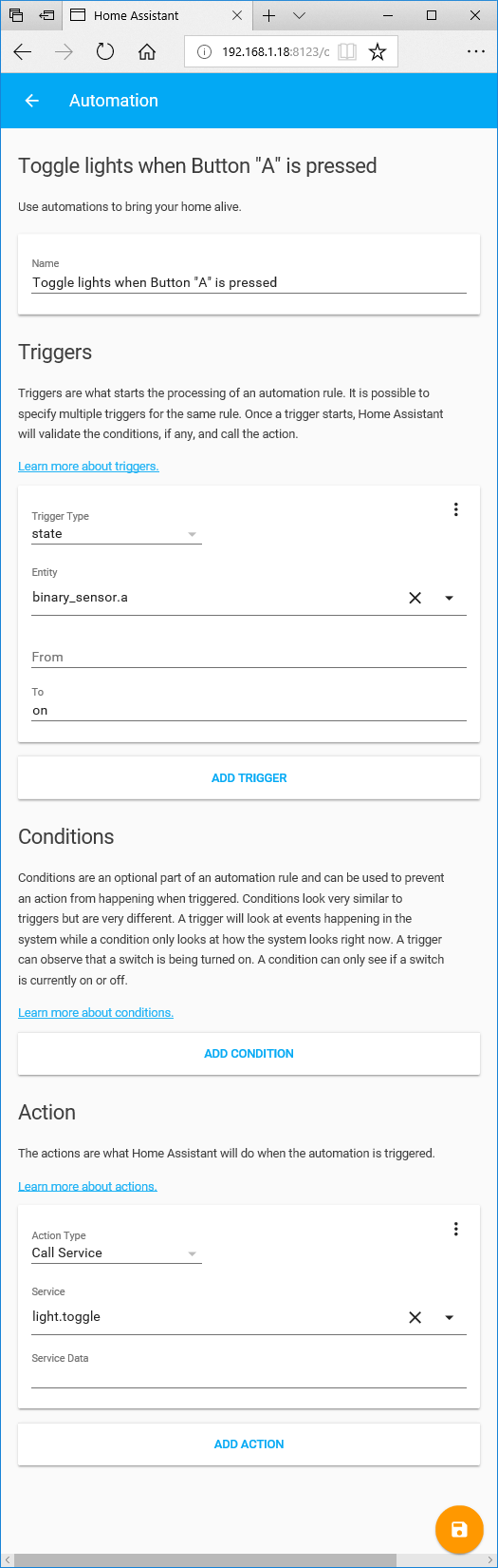
And create a new automation like this (don’t forget to click Save):
Option 2: edit automations.yaml
Add the following to your automations.yaml file:
- action:
  - service: light.toggle
  alias: Toggle lights when Button "A" is pressed
  condition: []
  id: 'button_a_toggle_lights' # call this anything you want, as long as it's unique
  trigger:
  - entity_id: binary_sensor.a
    platform: state
    to: 'on'
Reload the automations (Configuration->General->Configuration Reloading->RELOAD AUTOMATION) and then you should be able to switch your light on and off like this:
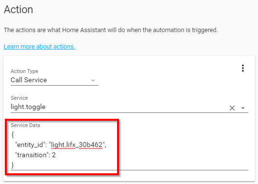
Note that light.toggle is called without any “data” (aka arguments/parameters), so it will target all lights and switch with an instant transition. If you want to switch a single light/group and add a smooth 1-second transition, you need to add a “data” block, like this:
- action:
  - service: light.toggle
    data:
      entity_id: light.lifx_30b462 # entity name of the light/group you want to target
      transition: 1
  alias: Toggle lights when Button "A" is pressed
  condition: []
  id: 'button_a_toggle_lights' # call this anything you want, as long as it's unique
  trigger:
  - entity_id: binary_sensor.a
    platform: state
    to: 'on'
Or in the web interface:
Configure other buttons to activate scenes
There’s two ways to do this - you can either set up an automation that directly controls lights, or you can set up a scene which controls the lights and then set up an automation that activates the scene. I’ll show you both ways.
Directly setting the lights
Let’s configure button B to turn the lights on and set brightness = 100% and colour temperature = 2700K, with a 1-second transition. (My lights are just white with adjustable colour temperature. If you have RGB lights, there are several ways to set the colour - see light.turn_on docs for details.)
Add the following to your automations.yaml file:
- action:
  - service: light.turn_on
    data:
      # entity_id: light.lifx_30b462 # uncomment if you want to control a specific light/group
      transition: 1
      brightness_pct: 100
      kelvin: 2700
  alias: Set lights to 100%/2700K when Button "B" is pressed
  condition: []
  id: 'button_b_set_lights' # call this anything you want, as long as it's unique
  trigger:
  - entity_id: binary_sensor.b
    platform: state
    to: 'on'
Reload the automations (Configuration->General->Configuration Reloading->RELOAD AUTOMATION) and then button B should turn your lights on to 100%/2700K.
Making a scene
Let’s configure button C = 50%/2000K and button D = 1%/1500K, both with a 1-second transition.
Add the following to your configuration.yaml file:
scene:
  - name: button_c # entity_id will be scene.button_c
    entities:
      group.all_lights: # change this if you just want to switch a single light/group
        state: on
        transition: 1
        brightness_pct: 50
        kelvin: 2000
  - name: button_d # entity_id will be scene.button_d
    entities:
      group.all_lights:
        state: on
        transition: 1
        brightness_pct: 1
        kelvin: 1500
Add the following to your automations.yaml file:
- action:
  - service: scene.turn_on
    entity_id: scene.button_c
  alias: Activate scene when Button "C" is pressed
  condition: []
  id: 'button_c_activate_scene' # call this anything you want, as long as it's unique
  trigger:
  - entity_id: binary_sensor.c
    platform: state
    to: 'on'
- action:
  - service: scene.turn_on
    entity_id: scene.button_d
  alias: Activate scene when Button "D" is pressed
  condition: []
  id: 'button_d_activate_scene' # call this anything you want, as long as it's unique
  trigger:
  - entity_id: binary_sensor.d
    platform: state
    to: 'on'
NB if you have set up LIFX cloud scenes, you can use those too - find the scenes’ entity_id by clicking the < > button under Developer Tools - but they won’t respond as quickly because the command has to be relayed by LIFX’s cloud server.
Restart Home Assistant to reload the scenes, and then your RF remote should work like a scene controller. Here’s a video:
Questions and Comments
If you have any questions or suggestions on how I can improve this guide, please leave a comment 🙂